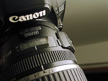
Canon A70 - IR Modification
I describe below how to modify a Canon Powershot A70 into an IR only camera by replacing the factory installed IR cut filter with an IR only passing filter.
By removing the IR cut filter, and replacing it with an appropriate filter that only lets IR radiation pass, we can create a highly sensitive, IR capable digital camera that opens up a whole new world of creative possibilities while retaining the convenience of digital photography.
Why did I choose the A70? There are no specific technical reasons, I merely had one at my disposal. This hack is not new and has been performed with numerous different camera models by many other people. However, as decent documentation is scarce, I believe this page might be worthwhile for someone.
Before I continue, a few words of caution. Please read them carefully!- The below documentation is for entertainment or educational purposes only. It is most likely incomplete, wrong, misleading, full of errors and omissions, and potentially hazardous to yourself and your environment. Peruse at your own risk.
- Understand that it is a very likely possibility that your camera will not survive the described modification. Don't attempt this if you don't feel the camera is expendable.
- The flash capacitor in the camera stores a possibly lethal current. While unlikely, if you have a known or unknown medical condition, or just bad luck, you could possibly kill your self. If you proceed, take the appropriate precautions. The only way to stay completely safe is not to attempt this modification at all.
- You agree to hold me free of any damages or injuries that should result from you or someone you know attempting the below modification.
Tools
You will need as a minimum the following tools and equipment:
-A set of 3 or 4 fine tweezers of various shapes
-A 1mm flat head screwdriver
-A Phillips screwdriver #000
-A TORX screwdriver #T4
-Packaging tape
-A permanent pen
-A clean work area
-A Cokin P007 IR pass filter or something equivalent to create a replacement for the IR cut filter.
-A dremel tool or similar to cut the replacement for the IR cut filter to its proper size. A small hand saw can be used as well, with 150 grain sand paper to sand the piece down to final dimensions.
Before you begin, have a good system to keep track of the screws and their original location:
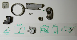
A large piece of packing or duct tape, turned around to expose the sticky side and fixed to your desk at it's ends is perfect. Draw outlines of the pieces you are removing directly onto the sticky side of the tape, label the drawn parts accordingly, then set down the screws at their approximate locations onto the tape while you disassemble. This will greatly help in preserving all screws and making sure they go back where they belong once you reassemble.
The Modification
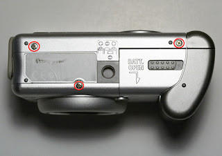
First you need to remove the 3 screws on the bottom of the camera.
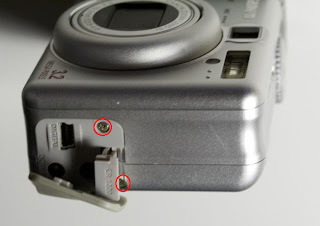
Open the cover for the connection ports. Remove the tray containing the CR1220 battery. You will see two screws which you need to remove.
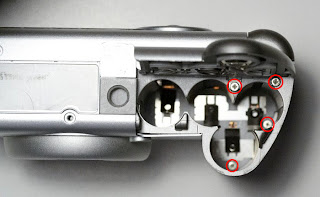
Open the battery compartment on the bottom of the camera. There are four screws that need to be removed. Two on top and two on the inside of the compartment.
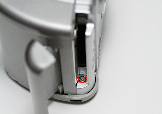
Open the CF card door and turn the camera on its head. There is another screw that needs to be removed.
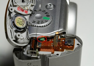
Now the top plate containing the zoom and shutter release comes loose. It attaches via a tiny green connector to the body of the camera. Disconnect and remove. The CF card door will now also come off.
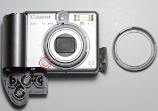
On the front of the camera, press the button marked with a red circle. This will allow you to unscrew the silver plastic ring around the lens.
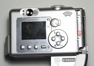
There is one last screw on the back of the camera that you need to remove.
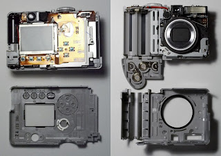
You will now need to carefully pry the plastic shell apart and off of the camera. Remove the back portion covering the LCD screen first, starting at the bottom and working yourself up. You will need to use some force, but not excessively so. It's more a question of feeling.
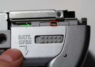
The cover for the battery compartment can be removed by pushing at the metal axis forming the hinge to the compartment in the direction of the green arrow with something like a paper clip. Watch the spring circled in red, you don't want it to go flying across the room.
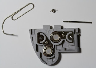
This is what you end up with once the lid has been removed.
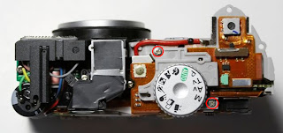
Now remove the mode dial at the top via the two screws holding it.
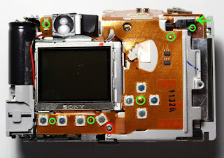
Before you proceed, take note of the "huge" capacitor to the left. It temporarily stores the power for a flash discharge and is probably loaded to full capacity. To prevent it from discharging via an accidental touch, possibly seriously hurting or even killing you or frying any equipment you might be touching at the time, I suggest you cover the terminals on top with electrician's tape for insulation.
Next, you need to remove the flexible circuit board covering most of the top and back of the camera. Start by removing the one screw holding it at the bottom.
Next, push the black lever to the top left inwards, so that you can remove the switch registering if the CF card door is open or shut. Be careful you don't push the black lever in too far, or it will come off and you will be hunting for it and the spring that usually pushes it back out. NOTE: this needs to work perfectly again when you put the camera back together. If not, the camera will think the CF card door is open and will NOT turn on. Be careful and take your time.
Now carefully remove the flexible circuit board from the body by lifting it off of the green circled notches one by one.
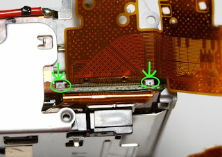
Once you have pried it completely loose, you will see where it attaches via a connector to one of the main circuit boards. carefully lift the green circled tabs with a small screw driver to unlock the connector and you will be able to pull the flexible circuit board completely off.
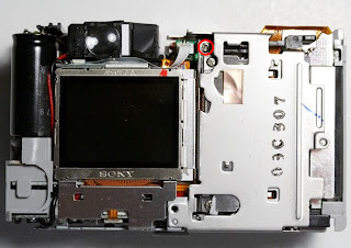
Now that the circuit board is removed, you can continue by removing the CF card reader. Remove the single screw circled above. Then, slowly slide the CF reader off of the rest of the body, towards you. You might need to lift it over a tab at the bottom of the camera.
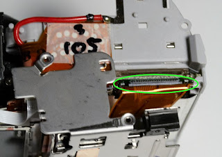
Once it is almost off, separate the connector between the reader and the underlying DIGIC processor board by simply pulling back on it.
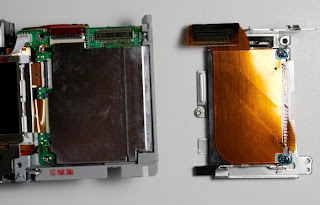
This is what it will look like once it has been separated.
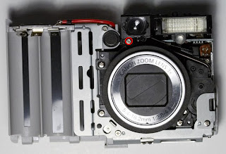
Next is the LCD screen. But before you can remove it, you need to remove the optical viewfinder first. There is one screw on the front that you need to remove.
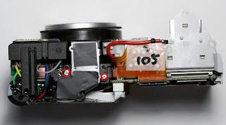
Then there are two more on top. Once removed, you can lift the viewfinder off of the top carefully. Take note that it is snapped in place in front where you removed the first screw. You will need to wiggle a bit for it to pop loose.
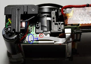
Under the area where the viewfinder was you will find the first screw that holds the LCD panel. There is a white ribbon cable in front of it. You will need to remove the ribbon cable eventually, so you might as well do it now by pulling it out of the marked connector which does not have a locking mechanism. Then remove the screw.
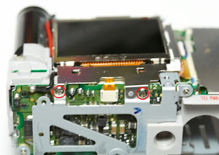
On the bottom of the camera, there are two additional screws to remove that fasten the LCD to the body.
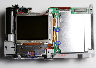
As a last step, before you can remove the LCD, there are 2 more ribbon cables to detach - marked in blue above. The one on the side has a locking mechanism that is unlocked by moving the two blue circled pieces of plastic in the direction in which the cable detaches.
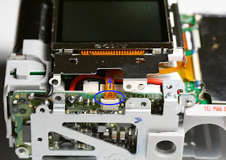
The smaller one on the bottom can just be pulled out.
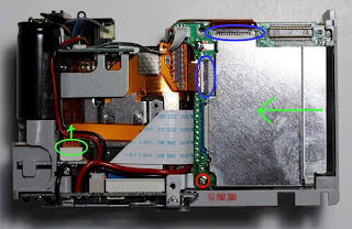
Once the LCD is removed the DIGIC processor board to the right ist last before we have access to the sensor. Start by detaching the additional 3 ribbon cables marked above. The green circled one just pulls out, the blue circled ones need to be unlocked first by flipping the black plastic flap on top of them open. Next, remove the screw circled red and you should be able to wiggle the DIGIC board out of the plastic holding it to the body.
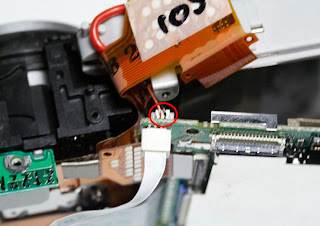
Once it is loose, there is a tiny connector on top that needs to be detached.
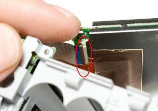
Finally, on the back of the board there is another ribbon cable that needs to be disconnected before you can completely remove the board.
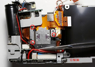
Now you have direct access to the CCD sensor of the camera. It is fastened by three TORX screws. The top left one will be covered by the piece of metal holding the flash capacitor. Just carefully bend it to the side and out of the way.
If you have not done so yet, make sure you have a well protected, dust free place to put the sensor while you remove the IR cut filter. Check the metal housing of the sensor to see if it might be secured by one or two small drops of glue. If so, carefully scratch the glue away with a screw driver or an exacto knife. Take extreme care not to cut or otherwise damage any of the ribbon cables. Then unfasten the screws and carefully lift the sensor off by its ribbon cable.
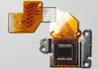
This is what the CCD sensor looks like after being detached.
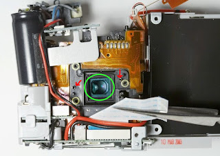
Here you can see the slightly blue tinted IR cut filter that we will be replacing by an IR only filter. Before we proceed, take note of the 3 brass shims around the screw threads holding the sensor. Also, note the two small springs marked with red arrows above. You want to be extremely careful not to lose any of them.
Carefully pull off the rubber gasket around the IR cut filter with a pair of tweezers. Then, using a screw driver, pry off the IR cut filter which is held to the plastic beneath by 2 tiny drops of glue.
Once the IR cut filter has been removed, fabricate a replacement piece out of the Cokin P007 IR filter, or whatever material you will be using. If you do not replace the IR filter with something of similar thickness and refractive index, your camera will be extremely near sighted and unusable except maybe for macros.
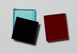
Above you can see the original IR cut filter in blue. As I was unable to obtain a P007 IR pass filter on short notice, I used a P003 red filter for the replacement (seen to the right) and added a piece from a thin gelatin IR filter so it would still be IR only.
Install your filter replacement in the same spot that the IR cut filter occupied and secure it with 2 additional drops of an appropriate glue. Two tiny strips of tape will work as well. Now put back the rubber gasket around the filter and re-attach the CCD sensor carefully.
Congratulations, you are almost done! Now you only need to put the whole thing back together again by retracing your steps and assembling in reverse order. Pay specific attention when re-attaching all those ribbon cables and other connectors. You want them connecting the right way around, coming together again securely and locked in place where supported. All the while you do not want to exert excessive force on any of them. Check each connection thoroughly before you move on. I would guess that 90% of the problems you might have on reassebly will be bad connections.
Good luck!!!
 Next, you have to dislodge the main flexible cable assembly. For this, you'll have to remove the tape (red arrow). Then slightly push up the flexible cable assembly (blue arrow). This is held down with some sort of sticky glue. You should be careful, and it will come off easily. Then, slightly push from under using a watch flat screwdriver (yellow arrow) to make this part of assembly come. It is held down by plastic tabs (visible in the pic). Next, the assembly will have to be taken out from under the plastic tab (grey arrow). Since the cable is flexible, you should be able to do that very easily:
 Tape off:
 And cable assembly removed from under the plastic tab:
 Next, take off the five screws:
 And slightly push the tab slightly, to make it come off:
 Only the slightest wiggling will make the top and bottom part separate. They're still connected through the cable assembly, so don't try to take the two halves apart:
 This exposes the problem. Broken gears in the gearbox:
 This is not a difficult fix. This pair of gears is available on ebay for $12.50, including shipping. Seems like in this case at least, the root cause was dropping the camera, and not sand from the beach, as I'd initially thought, though the sand particles are still there.
 The lens assembly can further be taken out to clean up the dust and sand particles etc.:
 Now to bust an urban myth. The camera with a stuck lens does not repair itself by blowing air through it by using a compressor, or thumping it, or throwing it against the wall. In this case, severe thumping/ buggering has resulted in not just the tabs on lens cover to be broken (red arrows):
 remove the green and red screws. the green screws are identical. take off the back cover. the back cover snaps together with the front cover at the top of the camera.
 remove the screw and take off the front cover. there's a thin dust ring between the cover and the lens barrel, don't lose it.
 remove the screws. the red screw is a metal screw. pry off the plastic io panel and tripod thread assembly.
 if you want to, now is the time to turn back first remove the two screws holding the control panel pcb, then disconnect and remove the control panel. very carefully disconnect the cables. the connectors are very delicate, and if you snap one, you'll be buying a new camera.
 desolder the circled wires. it is not necessary to detach the crossed wires. remove the three screws holding the main pcb (not indicated here), and reflect the main pcb along the bottom, exposing the sensor.